《But How Do It Know-The Basic Principles of Computers》读书笔记
Just a Little Bit
There is only one kind of thing in computer. It is called a bit.
A bit is always in one of its two possible states, either off or on, and they change between on and off when they are told to do so.
A computer bit is just a place, if there is no electricity in that place,then the bit is off. When electricity is present, then the bit is on.
The most basic part

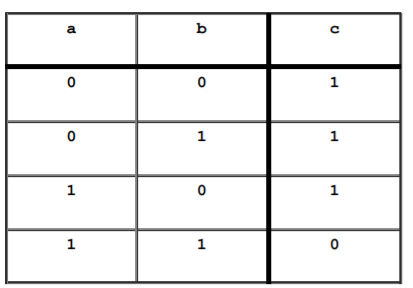
This is the most basic part that computers are made of. It’s called NAND gate. NAND gate is a simple device that has three connections where there may or may not be some electricity.
This type of computer part is in fact the ONLY type of part required to build a computer.
The two wires on the left (a and b) are the inputs where electricity may be put into the device, and the wire on the right (c) is the output where electricity may come out of the device.
The chart shows how the various input combinations create the output(0 means off, 1 means on) :
Simple Variations
NOT gate:


AND gate:


Remember When

The diagram shows one bit of computer memory.
‘I’ is where we input the bit that we want to remember, and ‘o’ is the output of the remembered bit. ‘S’ is an input that tells these gates when to ‘set’ the memory.
With ‘s’ on, ‘o’ does whatever ‘i’ does. With ‘s’ off, ‘o’ stays the way it and ‘i’ were, at the last instant just before ‘s’ went off. Now ‘i’ can change, but ‘o’ stays the way it was.
The chart can be simplified:

Eight Is Enough
In order to be able to represent something more than simple yes/no matters, what we are going to do is to stack up eight bits in a single package, and use them as a single unit.
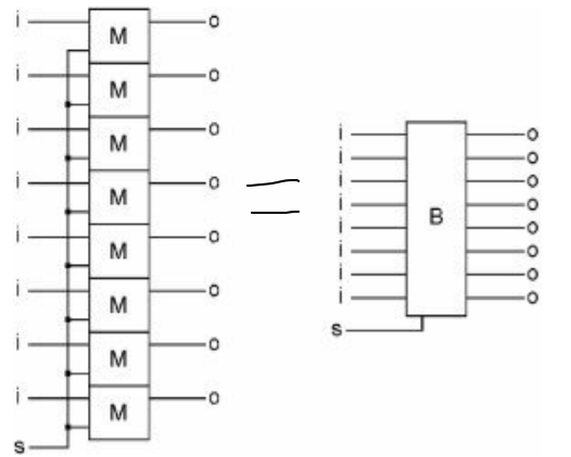
When the single ‘s’ gets turned on and then off again, all eight of these ‘M’s will capture the states of their corresponding ‘i’s at the same time. This assembly has a name; it is called a byte. A byte can represent 256 states.
Codes
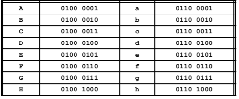
Now that we have 256 possibilities. The first things that might fit the bill is written language. In order to “put” an ‘A’ into a byte, we will use a code to associate one of the possible states of the byte with something that exists in the real world.
The letter ‘A’ will be represented by a particular pattern of 1s and 0s in the bits of a byte.
The most commonly used code is ASCII (American Standard Code for Information Interchange).
Back to the Byte
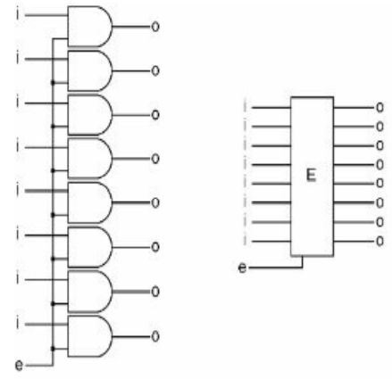
These eight AND gates, together, are called an“Enabler.” When ‘e’ is off, whatever comes into the Enabler goes no further. When ‘e’ is on, the inputs go through the Enabler unchanged to the outputs, ‘o.’
An Enabler allows a byte through when the bit ‘e’ is 1 and stops the byte when it is 0.
Register:
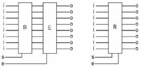
Register simply means a place to record some kind of information, Every time you store a new state in a computer register, the previous state of the eight memory bits is lost. The only thing that is in there is the most recently saved value.
The Magic Bus
we can simplify, and replace it with one of these:


When there is a connection between two of these bundles of wires, one wire of each bundle is connected to one wire of the other bundle as shown in the diagram on the left.
This grouping of eight wires is so common inside computers that it has a name. It is called a bus.

In the example, we have a bus, and there are five registers, each of which has both its input and output connected to the same bus.
All of the ‘s’ bits and ‘e’ bits are off. If you want to copy the information from R1 into R4, first you turn the ‘e’ bit of R1 on. The data in R1 will now be on the bus, and available at the inputs of all five registers. If you then briefly turn the ‘s’ bit of R4 on and back off, the data on the bus will be captured into R4.
So this is a bus. It is a bundle of eight wires that typically goes to many places.
More Gate Combinations
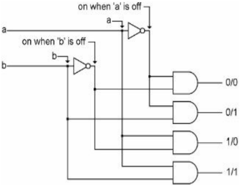
This combination is called a decoder.
The name means that if you consider the four possible states of the two
inputs as a code, then the output tells you which of the codes is currently on the input.
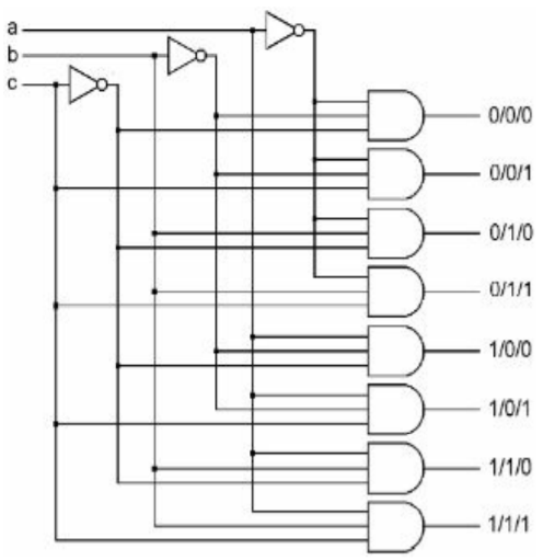
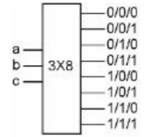
This can be extended. If we added a third input, there would then be eight possible input combinations.
First Half of the Computer
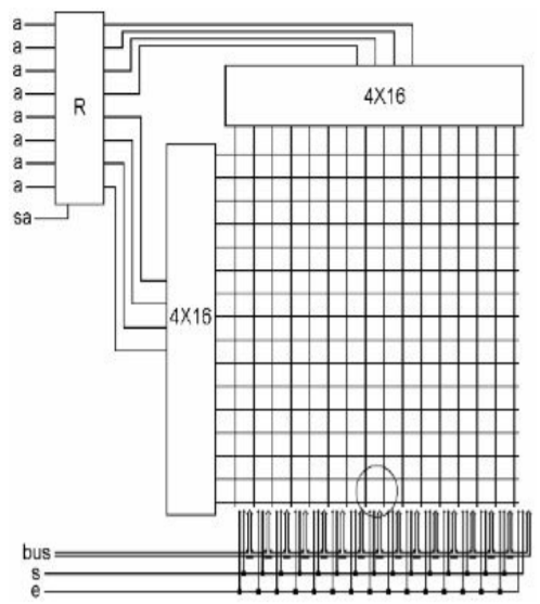
We start with a single register. A combination of bits is placed on the bus and the ‘sa’ (set a) bit goes 1 then 0. That bit pattern is now stored in this register. The first four output bits are connected to one 4X16 decoder, and the other four output bits are connected to another 4X16 decoder.
Of these 256 intersections, there will be only one intersection where both the horizontal and vertical wires are on. Which intersection that is will change every time the value in R is changed.
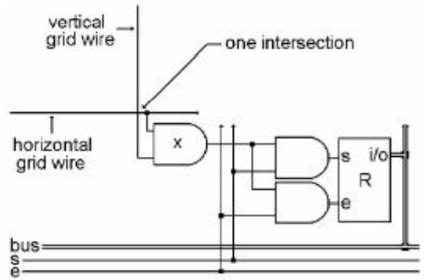
There is a circle on the diagram above, around one of the intersections of the grid.
There is only one intersection where both grid wires are on. Therefore there is only one intersection has its ‘x’ gate on, and its register can be set from the bus, or its contents can be enabled onto the bus and sent elsewhere.
The above is the computer’s main memory. It is half of what is necessary to build a computer.
This is a good type of memory to use if you want to be able to access the bytes of memory in a random order. So this type of memory is called “Random Access Memory,” or “RAM”.
It uses 257 registers. 256 registers are memory storage locations, one register is used to select one of the storage locations and is called the “Memory Address Register” or “MAR”.
A larger RAM:
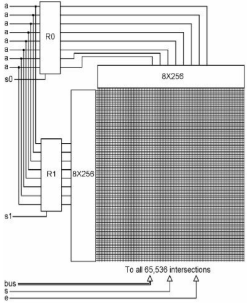
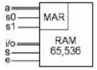
Number
The binary system
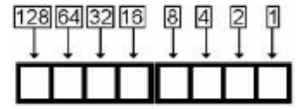
In the binary system, each position is worth two times the amount to its right.
The Other Half of the Computer
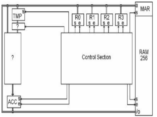
We will call this half of the computer the “Central Processing Unit,” or CPU.
“Control Section” controls all of the ‘set’ and ‘enable’ bits in the CPU and the RAM.
R0, R1, R2, and R3 are registers that are used as short- term storage for bytes that are needed in the CPU.
The register called ‘TMP’ means temporary. Its input comes from the bus, and its output goes downward.
The last register is called the accumulator, or ACC.
More gate
OR gate
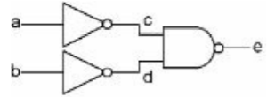
simplified diagram:

XOR gate
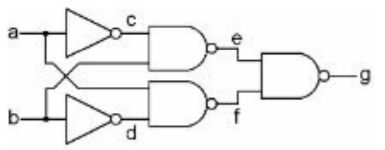
simplified diagram:

Bytes Operation
The Left and Right Shifters
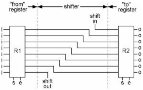
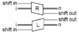
This shows two registers connected by a right shifter. The one at the bottom (shift out) is often connected back to the one on the top (shift in).
The NOTter
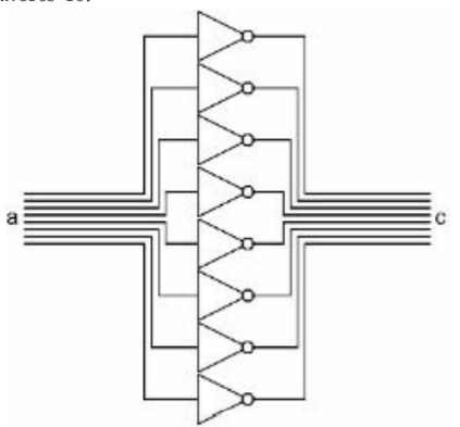

This device connects two registers with eight NOT gates.
Each bit will be changed to its opposite.
The ANDer
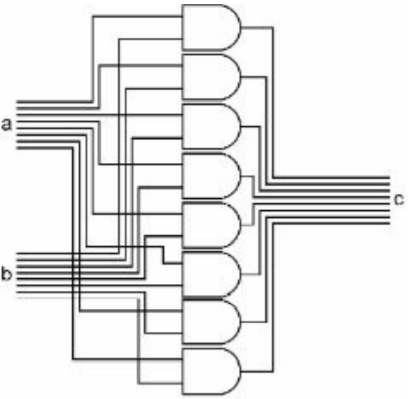

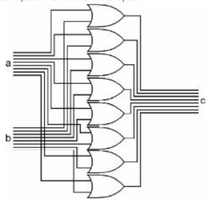
The ORer

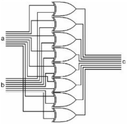
The Exclusive ORer

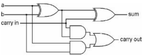
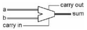
The Adder
Adding three bits:

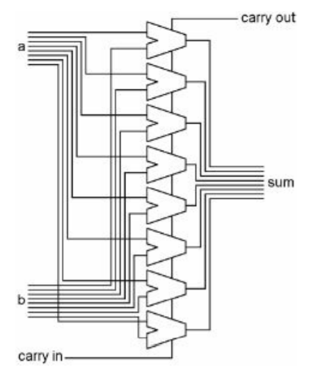
Adding two bytes:
The Comparator and Zero
Here is one bit of the comparator:
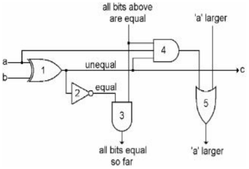
Gate 4 turns on if three things are true.
- Bits ‘a’ and ‘b’ are different.
- Bit ‘a’ is the one that is on.
- All bits above this point have been equal.
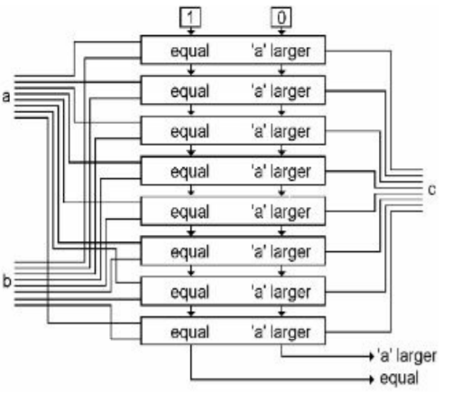
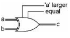
Two bytes comparators:
The Arithmetic and Logic Unit
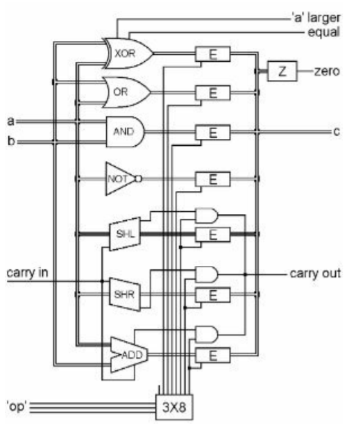
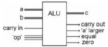
We are going take all seven of these devices, put them together in one unit, and provide a method of selecting which one of these devices we want to use at any given time. This is called the “Arithmetic and Logic Unit,’ or “ALU”.
More of the Processor
There is one more little device we need:
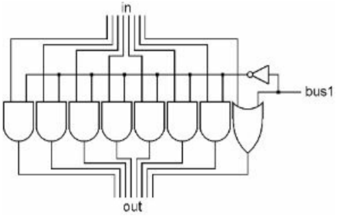
When the ‘bus 1’ bit is off, all of the bits of the input bus pass through to the output bus unchanged. When the ‘bus 1’ bit is on, the input byte is ignored and the output byte will be 0000 0001.
The CPU diagram
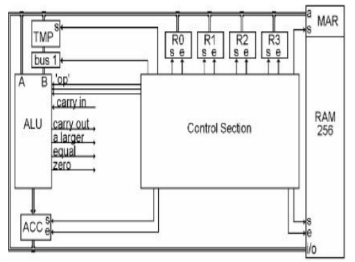
For a two input ALU operation, there are two steps. First we enable one of the registers onto the bus and set it into TMP. Then we enable the second register onto the bus, choose the ALU operation, and set the answer into ACC.
Clock

This graph shows bit ‘X’ going on and off, on and off regularly. When something repeats some action regularly, one of those actions, individually, is called a cycle.
One Hertz (or Hz for short) means that the electricity is going on and off once per second.


This bit is called the clock. These days it is well over a billion times per second, or several gigahertz. This is one of the main characteristics that computer companies tell you about to show you how great their computers are.

'clk d' will delay the electricity about one quarter of a cycle.

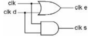
‘clk e,’ which stands for clock enable, and ‘clk s,’ which stands for clock set.
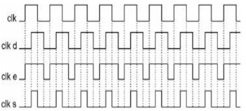
This meets our requirements of needing to first enable the output of a register, and then, after the data travel down the bus, to turn the set bit of the destination register on and off before turning the enable bit off at the first register.

Doing Something Useful
Add R0 and R1 to R0:
- first clock cycle : enable R1 onto the bus, and set it into TMP.
- second cycle : enable R0 onto the bus, set the ALU to ADD, and set the answer into ACC.
- third cycle: enable ACC onto the bus, and set it into R0.